C15 sailboat - modified experiment boat
Jump to:
Rotating mast/ rotation inducer
-------------------------------------------
General (C15 or Coronado 15)
15' 4" length Overall
5' 8" Beam
385 Lbs weight
123 sq foot Sail - Day Sails
139 sq foot Sail - Performance Sails
This boat was designed around a crew of two, one crew on a trapeze. It has no ballast except the pilots, is not self righting. Its lightweight, relatively narrow, sail area and bottom shape make for a fast planning sailboat primarily used for racing.
However... I didn't know any of this when I bought the boat and this didn't exactly fit my application (a C14.2 or a C16.5 might have been a better choice had I known better). I use this boat for "after work" sailing sessions in gusty wind and if you need crew, it really limits when and how often you can sail. So I really wanted and needed a single hand boat. One of the first times I took the boat out, I got knocked down and not knowing any better, did not get the boat up-righted quickly, the mast sank, the boat filled with water internally and the boat ended up turtled with the mast tip stuck on the lake bottom.
So, while the C15 is a great performing sailboat for its intended application, I was about to sell the boat. Instead, I just decided to make it into an experiment boat Also to point out is that I primarily sail this boat at between 5200 to over 9000 foot elevation and its in the mountains. You have to have something that will handle gusty and fast changing winds. Some of the modifications are to extend the wind range of the boat on the water.
The first major mod I did was to add essentially two bags of concrete (see concrete update below) and a group 24 battery just under the mast and as low as possible. This was a big risk (cut the boat up with a chain saw then burn it if this didn't work) but this ended up a change I've been very pleased with. One way to look at this is that its like having a 200 or so pound crew member that doesn't move curled up around the mast and as low in the boat as possible. I have been sailing a 1990 Macgregor 26S water ballast boat for a bunch of years so am familiar with a "high location ballast".
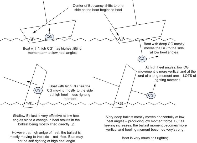
Why I think this high location ballast seems to be working well on this "planning hull" boat.. Righting moment results from lifting a mass against gravity so it is vertical movement of the mass that matters. The lifted mass is at the end of a "moment arm" from the boats center of buoyancy which starts out at the center of the boat but rapidly moves outward as the boat begins to heel. As expected from the concept in the figure below, the 160 pounds of ballast is effective at low heel angles where it returns a good (and possibly particularly good) investment of righting moment per added weight. The goal with adding weight is to maximize the righting moment per added weight. The high ballast location like this implementation is very good at this goal at low heel angles but very poor at high heel angles.
This boat still likes to get on a plane as the 160 pounds of ballast is overall "relatively small amount of weight" but the weight significantly improved the stability of the boat at lower heel angles. The tradeoff with the high ballast location is that at very high heel angles, the ballast weight is just moving sideways and not providing much righting moment. Also, many boats with high location ballast have a high freeboard which also helps keep them self righting. However, this boat has fairly low freeboard and is not self righting. Because of this, I have a float at the top of the mast.
For the above reasons, this boat is best sailed at low heel angles (which is also best for planning). If you get it up to a very high heel angle, it loses its righting moment and will still go over like the original design. The Hobie float at the top of the mast makes the boat very easy to get back upright if you do go over (stand on the centerboard) as it keeps the hull from taking in any water and if I'm using an outboard, also keeps the outboard dry (note, the Hobie Bob was replaced with this Mast head float experiment )
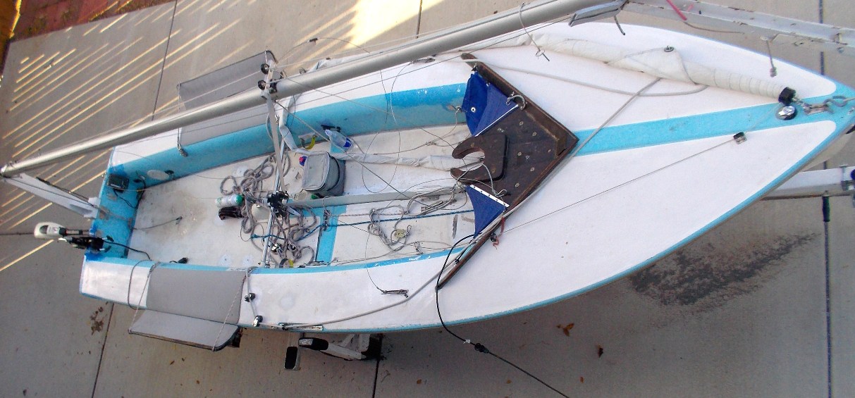
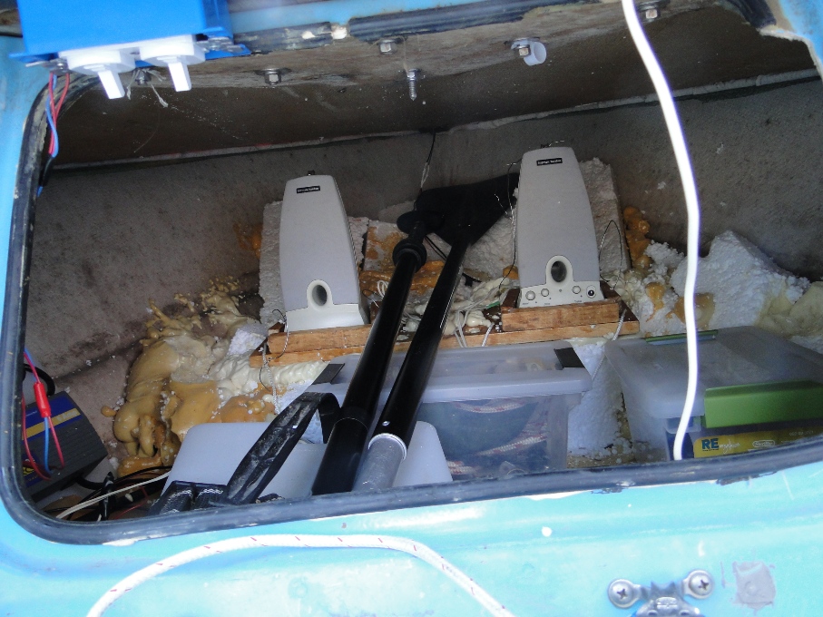
Below - access for concrete just behind the mast. There is also concrete just in front of the mast base in the cubby area. In both cases, the concrete is as low in the hull as possible. The hull pieces cut out for the ballast access were glassed back in after the concrete was added. Option - I could have made this area so that I could add or remove ballast but am overall pleased with it as is.
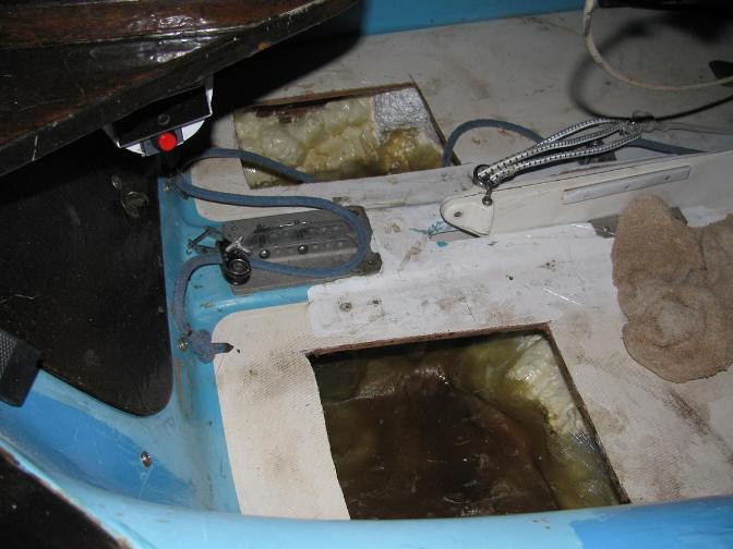
Concrete update. I had put two "80 pound" bags of concrete in the hull. One bag in the two compartments in the picture above and the second bag was put in around the battery in the cubby just forward of the mast base. I recently REMOVED about 20 pounds of concrete from the most forward part of the concrete in the cubby area. The ballast weight gives righting moment working against a center of buoyancy that has moved to the side of the hull during heeling. So putting the ballast at the widest part of the hull gives the maximum moment arm for the ballast mass working against the center of buoyancy. Where the ballast weight was removed, the hull was narrowing towards the bow of the boat and probably wasn't an initial good choice (??).
After removing the 20 pounds of the most forward concrete, I really could not tell any difference in the way the boat sailed. The goal is to have as much righting moment as possible and there are two ways to do this. Increase the moment arm length between the force that is being lifted and the pivot point by having the ballast near the widest part of the boat - or increase the weight that is being lifted. But increasing weight also increases hull drag. The 20 pounds that was removed from the very forward area had the smallest moment arm length and is probably why I didn't notice much change in stability. But removing 20 pounds should help planning threshold at least a little.
------------
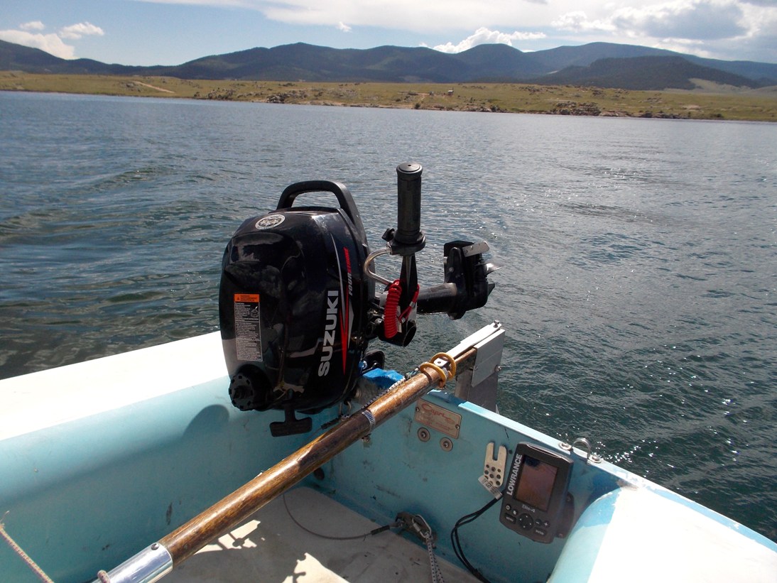
I also like an outboard (several ramps I launch at would be a huge pain without an outboard and you get in and out of the ramp area faster). If I'm at a big lake, Ill put a 2.5 hp four stroke Suzuki (about 31 pounds) on the boat. If I'm primarily sailing on a smaller lake, I use a 30 pound thrust electric trolling motor since it only weights 13 pounds - weight on the transom is not good if your trying to keep the boat fast. There is a group 24 battery just in front of the mast that powers the trolling motor. The battery stays in the boat regardless of which outboard is used since the battery location makes it also effective as ballast. Boat plus trailer 748 pounds.
The 2.5 hp gas outboard moves the boat at about 6.5 mph and can get the boat back to the dock in pretty much any condition. The 30 pound thrust electric trolling motor moves the boat at about 3.5 mph and there are conditions I have been in where I could not point the boat into the wind with the electric trolling motor but it has to be pretty wild. Assuming a 30 amp current use from the trolling motor at peak, I can get maybe 1.5 hours of run time from the group 24 battery or maybe about 5 miles range.
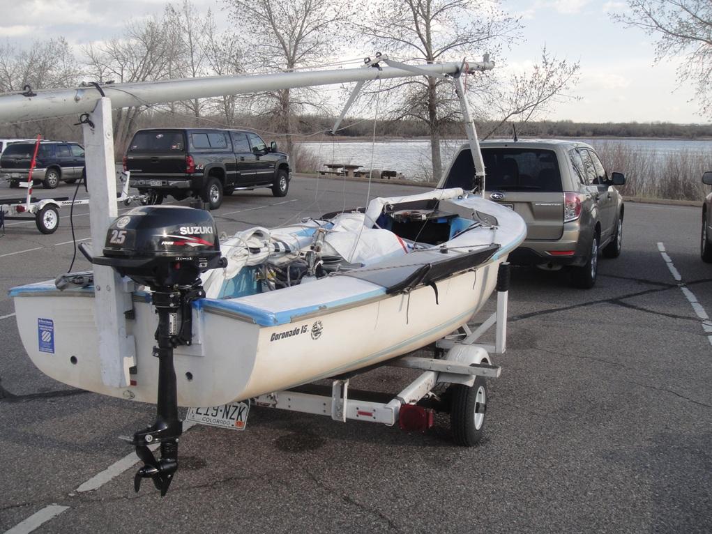
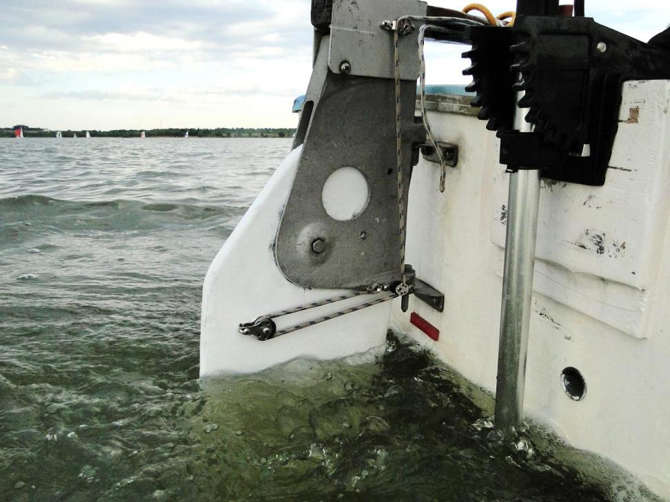
Below.. one day Ill get around to painting the boat (after I'm done cutting it up).. The outboard transom was lowered a little to work with the Suzuki 2.5 hp which is a short shaft. The short shaft normally works fine but with the small boat, if I move all the way forward (like going to the mast) with the outboard running, the water pump inlet gets "close" to coming out of the water which is not a good thing. Been using this now for a season, overall works well, no problem with the water pump coming out of the water.
![]()
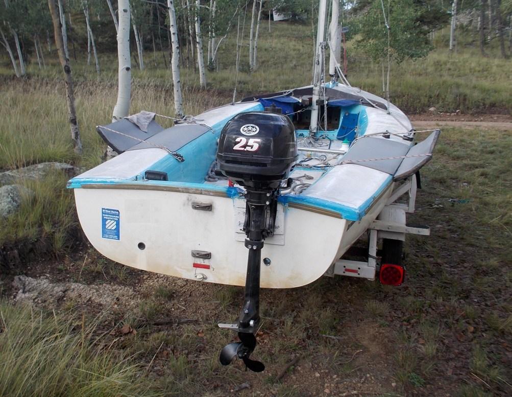
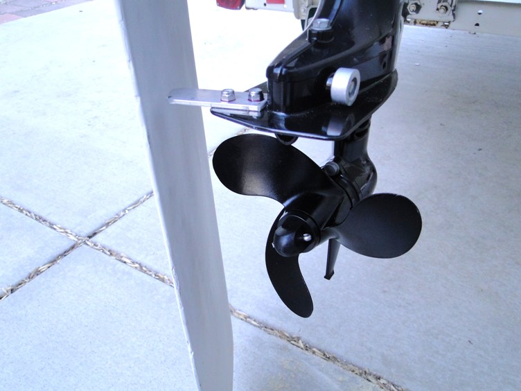
Below - gas outboard with the transom lowered where the motor clamps on as shown in the picture above. This was done to get the short shaft output "just a little" lower in the water since this outboard is water cooled and the pump inlet is near the prop.
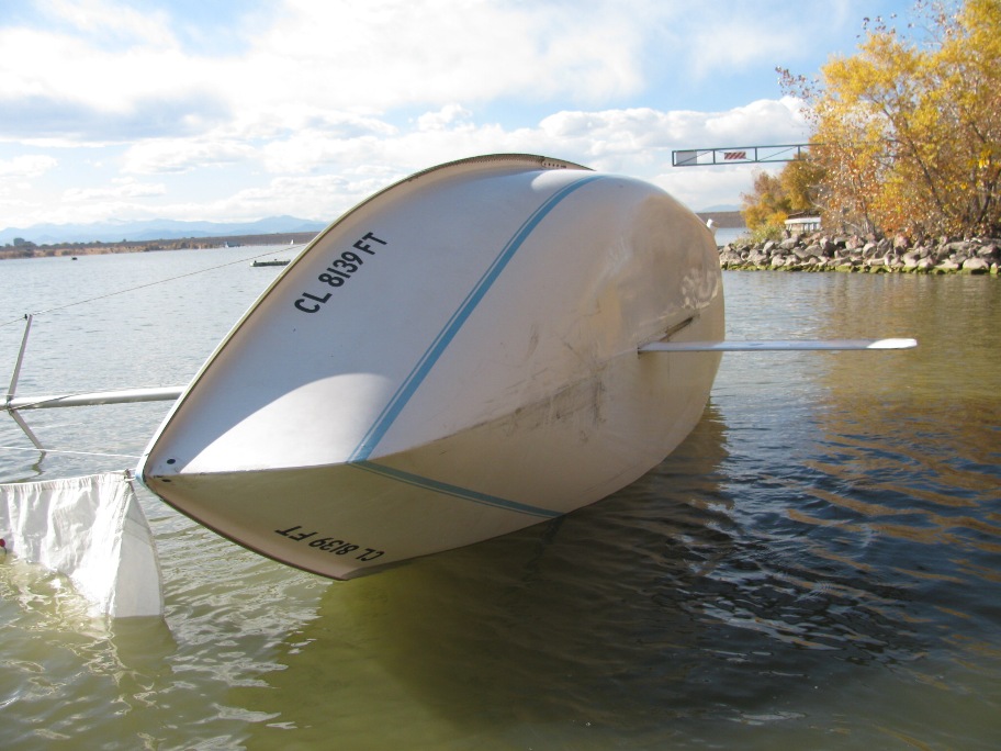
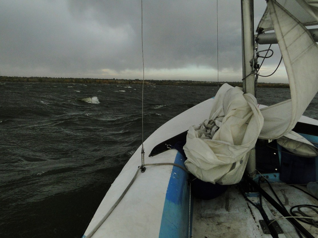
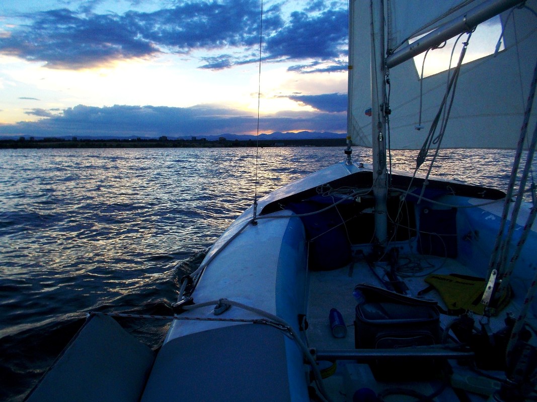
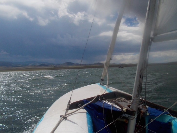
Below - this picture was taken just after a knockdown where the Hobie float made all the difference and I easily up-righted the boat after dropping the sails. Everything stayed dry and no water in the inner hull. This storm front came in amazingly fast and I had full sails up when it hit. The electric trolling motor on the boat could not make the boat go upwind (where I needed to go to get back to where I had launched) but I think the 2.5 hp gas outboard could have. This is before I added the jib furler - and this condition is one of the reasons I added the jib furler. Note that I still use the electric trolling motor 90% of the time I take this boat out sailing.
Below : I'm 57 years old (at the time these seats were put on the boat) but apparently like to sail like I am 30. I would go out and have a great day hiked out. The next few days I would be hobbling around barely able to walk with lower back pain. So some hiking seats were added. These are adjustable with the strap shown on the back side of the seat in the picture below. The seats are also easily removed or can fold up when at a dock. There are four holes drilled in the hull lip along the length of the seat and the line at the bottom of the seat threads the seat to the hull and still allows for some rotation of the seat. I just love these seats, they have made a big difference in the comfort of the boat for an older sailor.
More pictures of the hiking seat
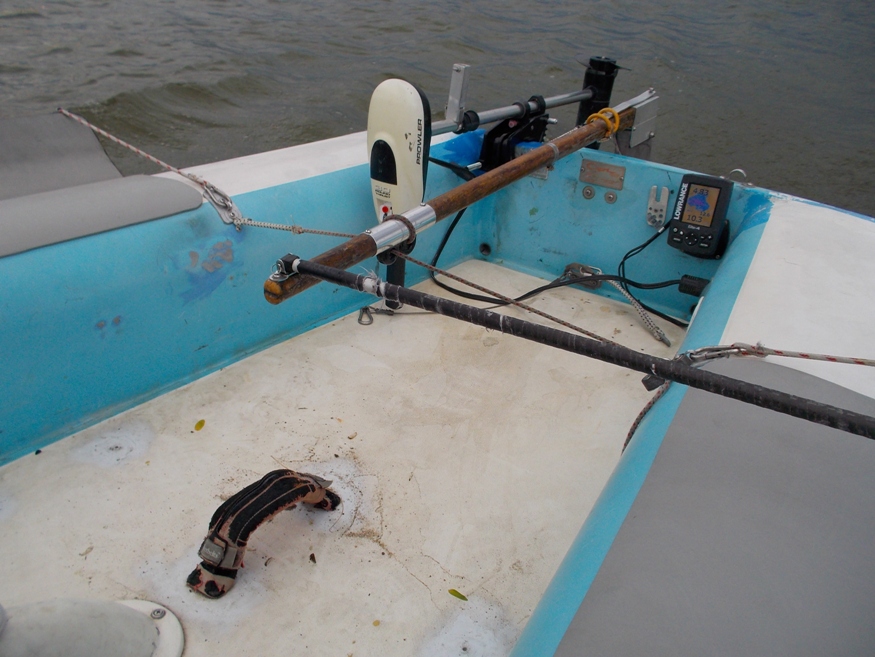
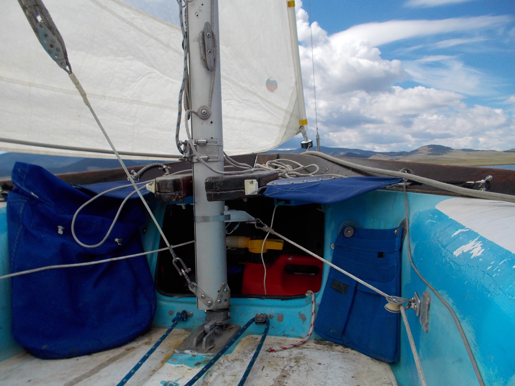
Below - jib sheets, mast rotation inducer, jib furler controls are all positioned for single handing.
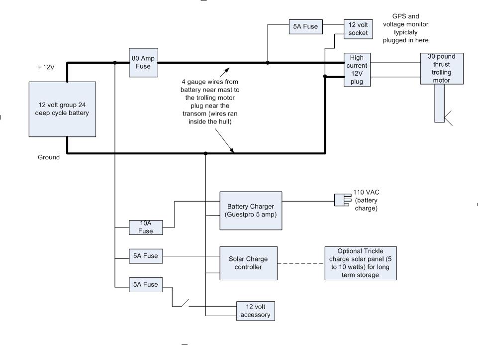
Below: Electrical system. The boat has a group 24 battery just in front of the mast that gets used as ballast. Normally this battery gets used with the 30 pound thrust electric trolling motor to get the boat in and out of the dock only (sometimes a little more if the wind drops) and also powers a GPS fish finder and often a computer speaker stereo system playing MP3 audio files. There is a battery charger always in the boat. At the end of a sailing session, I just plug the boat in while in the driveway and the battery is usually ready to go again within a few hours. .
Below: Electrical stuff is in the cubby just in front of the mast.

Below. 12 volt computer speakers play off a USB audio stick. Backup two piece paddle if from a stand up paddle board. I added a bunch of flotation foam to compensate for the ballast concrete I added. The boat already had a bunch of foam in the hull which I got to test when I first got the boat and filled it with water in a knock down.
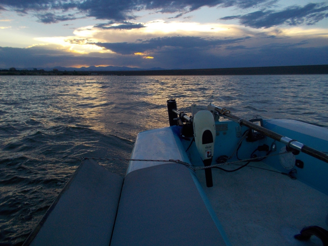
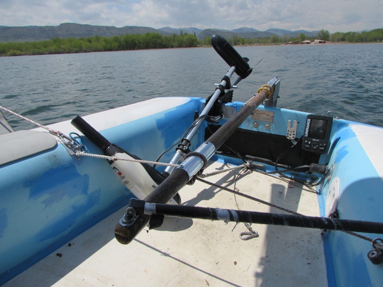
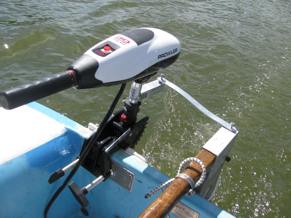
Below.. Err... why yes, that is a windsurfer foot strap for hiking, works great. There is a substantial anchoring system under the foot strap as it would not be a good thing to have it rip out while sailing. The trolling motor is pulled forward when its up to reduce the moment arm of the motor weight near the prop.
Below. Update - when sailing I try and get the weight of the trolling motor as far forward as possible to reduce the "moment arm" since most of the trolling motor weight is at the end of the shaft near the prop.
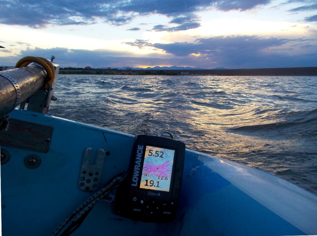
Below - depth finder and GPS gives speed and water depth. This unit will also display the battery voltage which is nice since I often have only an electric trolling motor on the transom.. It has a map feature that I normally don't use but it may come in handy on a large lake to find a cove. This unit also is relatively low power at about .18 amps. The only bad thing is that although it can be set up to keep track of peak speed, it is terribly inaccurate often giving false (too high) readings. .
Below bracket for a hand held VHF radio next to the GPS fish finder (might come in handy on one trip Id like to take with this boat).
Below: bracket added to outboard to keep prop from meeting the rudder.
Below. Connecting strap allows the electric trolling motor to rotate with the rudder. The strap folds over and stays with the tiller/rudder when sailing.
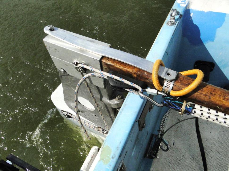
Below: both the centerboard and the rudder will kick up in a grounding. The rudder release is a little complicated to figure out from the picture below but a grounding will cause that bent oval bolt to move backwards pulling against the bungee and it will eventually slide up the jam cleat "ramp" and release.
Below - light weight centerboard is held down by the white/red line and the bungee cord. In a centerboard grounding, the top of the centerboard pulls forward and stretches the bungee and it can take a lot of abuse. I did this after pretty much ripping out the centerboard hinge hitting an underwater tree stump with a fixed pull down line. The blue line pulls the centerboard up and can also be used to keep the centerboard at varies angles between full up and full down (such as for a downwind run or running the boat in shallow water).
Rotating mast/ rotation inducer
Below set - rotating mast with rotation inducer (forces the rotated mast to one side or the other).
 \\
\\
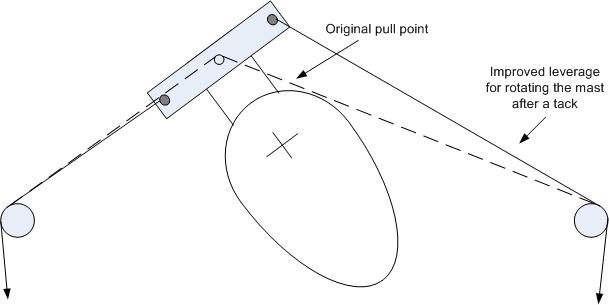
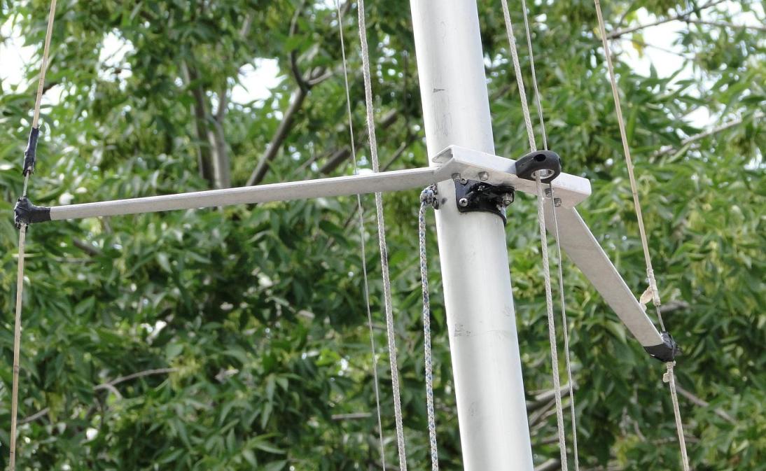
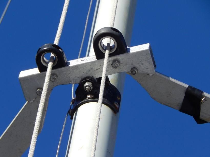
Below - the rotation inducer shown below works nicely now that the top bar was added. The rotation inducer is what made the rotating mast work on this boat as it keeps the mast rotated in high winds (it would sometimes pop to the wrong side just at the wrong time) and also keeps the mast from bouncing around if there is no wind but wakes from passing boats.
Notes regarding rotating mast. The largest rotating mast I have owned was on a H16 but understand on larger boats with rotating mast, the rotation control can adjust the angle of the mast. The mast on this boat has a relatively small cord length and that may have something to do with the mast seeming to work well fully rotated to one side or the other (no adjustment - either fully to one side or the other) and this is always how I sail the boat. Its possible this over rotates a little if I'm really trying to go upwind but cant say for sure. I "could" set any angle of the mast by adjusting the controls on both sides of the boat - but I never do this. I always fully rotate the mast. When I get ready for a transition, release the cleat on one side and when the boat is on the new tack, fully rotate the mast and cleat it on the other side (where I am now sitting). This seems to work very nicely but it may be partly to do with the smaller mast chord length.
 l
l
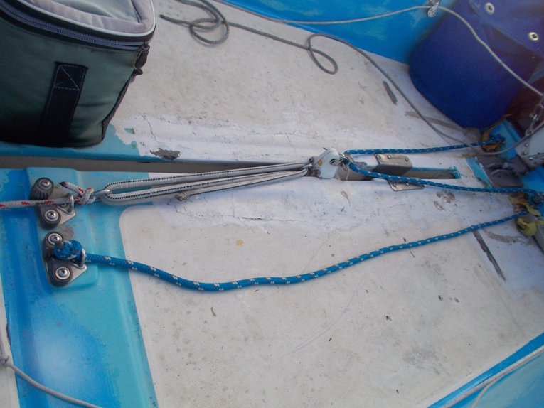
Below - rotation inducer controls. There is one on each side of the boat. The leverage is set up so that you pull from the side of the boat you normally would sit on for the correct mast rotation. The C15 setup allows this. Normally the rotation control on the front of the mast would interfere with the jib sheets but this is no problem with the C15 configuration as the jib sheets are always above the rotation inducer location.
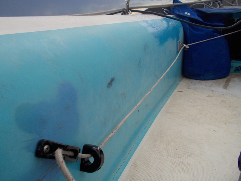
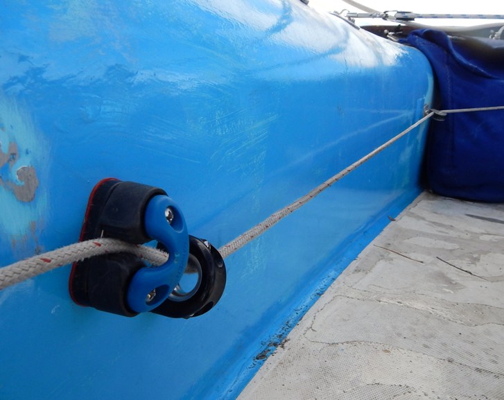
After using the above setup for while, I switched to the cleat below - works very nicely. Sometimes the jam cleat would slip out when it got a little wild, the cleat below both holds and releases well.
Below - latest version of the rotation inducer cleat (one on each side of the boat)
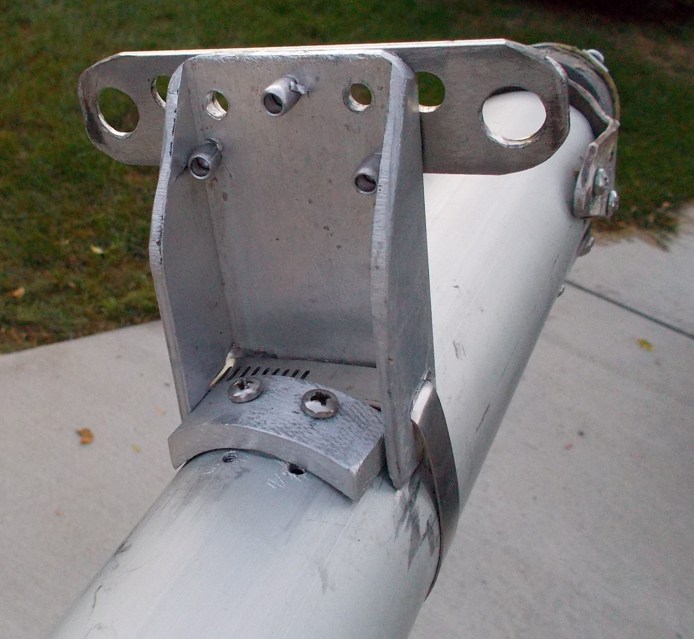
Below. The original mast base was removed from the bottom of the mast and modified to rotate.
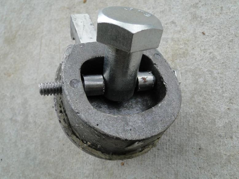
Below - bronze bearing washers are used to aid rotation
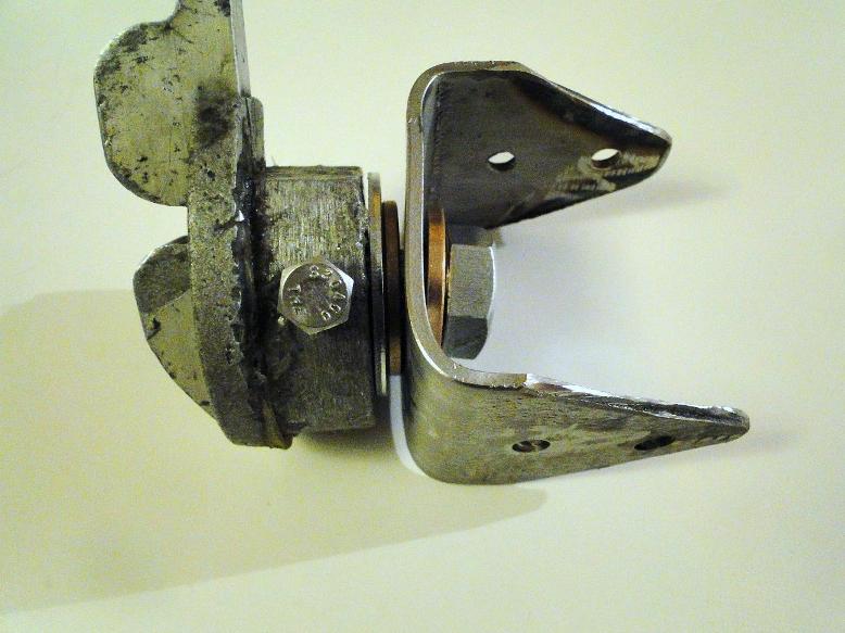
Below. The rotation pivot ended up moving closer to the mast leading edge than is shown in the picture below. The pivot being near the leading edge helps the mast self rotate.
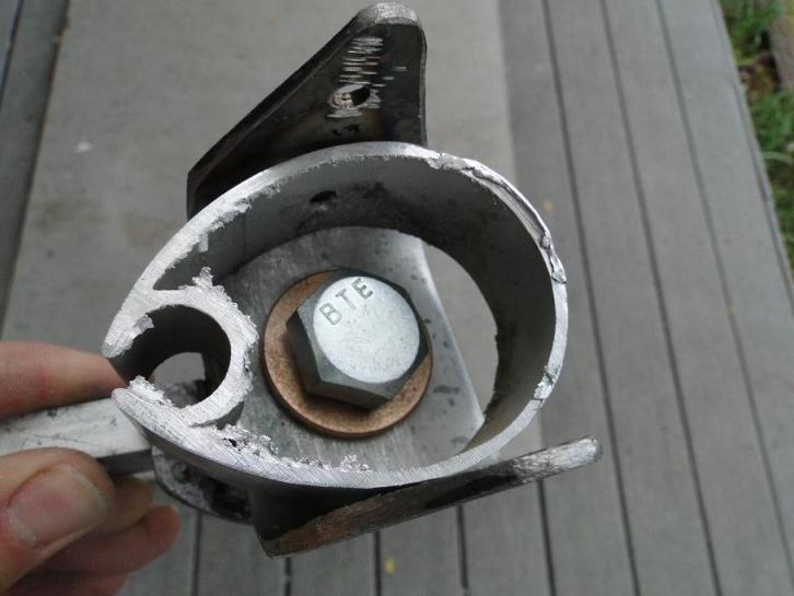
Below - final rotation base. Note that the pivot axis is about as far forward as I could get it as this aids the self rotation of the mast. The picture below was taken on the third season of use (many - many sailing sessions).
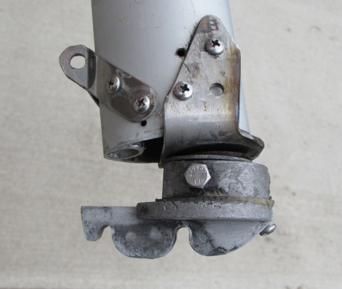
Below: rotating mast uses spreaders like the original configuration. The spreader must rotate and it is also what ends up limiting the rotation.
Below - rotating spreader assembly after three season and probably over 50 sailing sessions.
Below Rotated mast sailing (main alone) showing one other benefit and that is the better aligned air flow if your using a Hobie Bob float. The picture below shows another experiment on the sail and that is stiffening battens just behind the mast. This sail was fairly worn out and in high winds (before the battens were added), there would often be an "S" or baggy shape just behind the mast. Those added battens do a good job of keeping this from happening in higher winds. This was also something I had used years ago on ice boats with good results. The lee side of the mast and the area of the sail just behind the mast are where the largest velocity and pressures occur on the sail and both the rotated mast and leading edge battens help keep things as gentle as possible in this area in an effort to minimize local flow separation. Technical paper by Tom Speer on wing masts and sail flow in general LINK

Also regarding the main sail. I felt that there was a little more sail area than I needed for single handing so took another big risk and cut about 1 foot off the top portion of the mast. I then cut about 1 foot off the foot of the main sail and hand re-sewed it as a loose foot sail. A person who's opinion I respect told me I may ruin the sail doing this but I must have got lucky as I ended up liking the results. I have a nice adjustable outhaul and it does a nice job of tuning the sail for different wind conditions.
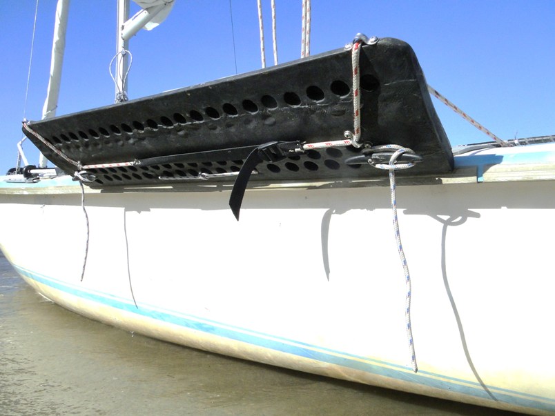
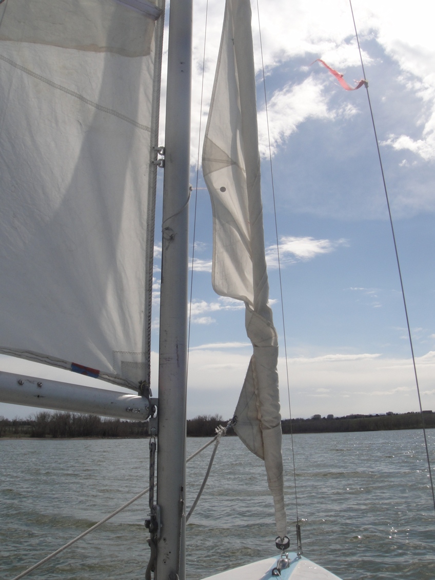
Below set.: The next picture shows a problem with at least the wire luft furler I used. The wire luft furler on the jib would have a hard time winding up the sail in high winds (where it almost always gets rolled up) as shown in the picture below. I solved this with a PVC leading edge stiffener (next picture after the one below). I really like the wire luft furler as it makes the boat very easy to set up and you don't need to baby it as opposed to a conventional semi rigid furler. When I take the boat down after sailing, I leave the furler attached at the bow and just drop the halyard (see the very first picture on this page to see where the jib and furler sit when I'm trailering the boat). The mast is still held up by the forestay (which is also a backup in case of a jib wire luft failure). .A 2 to 1 pulley leverage is used to get the jib halyard tension tight as this affects the upwind performance.
Below: two sections of PVC pipe were added to the leading edge. This greatly improved the furlers ability to roll the sail up in high winds. The two section of PVC pipe extend about 3/4 the length of the jib sail. The PVC pipe was run through a table saw to create the full length slot that fits over the wire luft. Each PVC section has three straps sewn to the sail to hold it in place similar to the strap at the bottom of the luft shown in the picture. A single small screw on the bottom strap keeps the PVC piece from sliding. Also to note in the below picture is the distance between the jib furler and the forestay which is about half a foot on this boat. This is distance is maintained for the length of the jib and is also important for safely rolling up the jib in high winds.
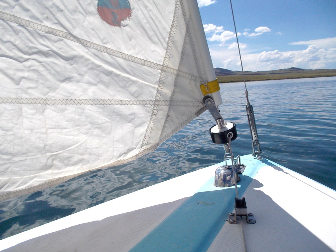
Below - with the PVC on the leading edge, the wire luft furler rolls up the sail much nicer when done in high winds. Since this is normally how this boat is reefed, the furler needs to work in high winds. Reefing this way is partly enabled by the rotating mast as the main works well just by itself.
The video below shows one of the benefits of the rotating mast - boat still sails nicely on just the main. This tippy narrow boat would be very hard to reef the main however its very easy to roll up the jib. So in high winds, the boat is often sailing on just the rotated mast main.
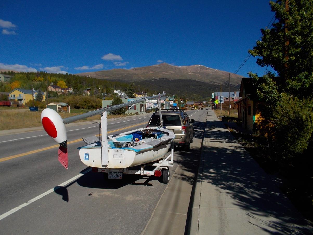
Below: towing through Alma Colorado elevation 10,578
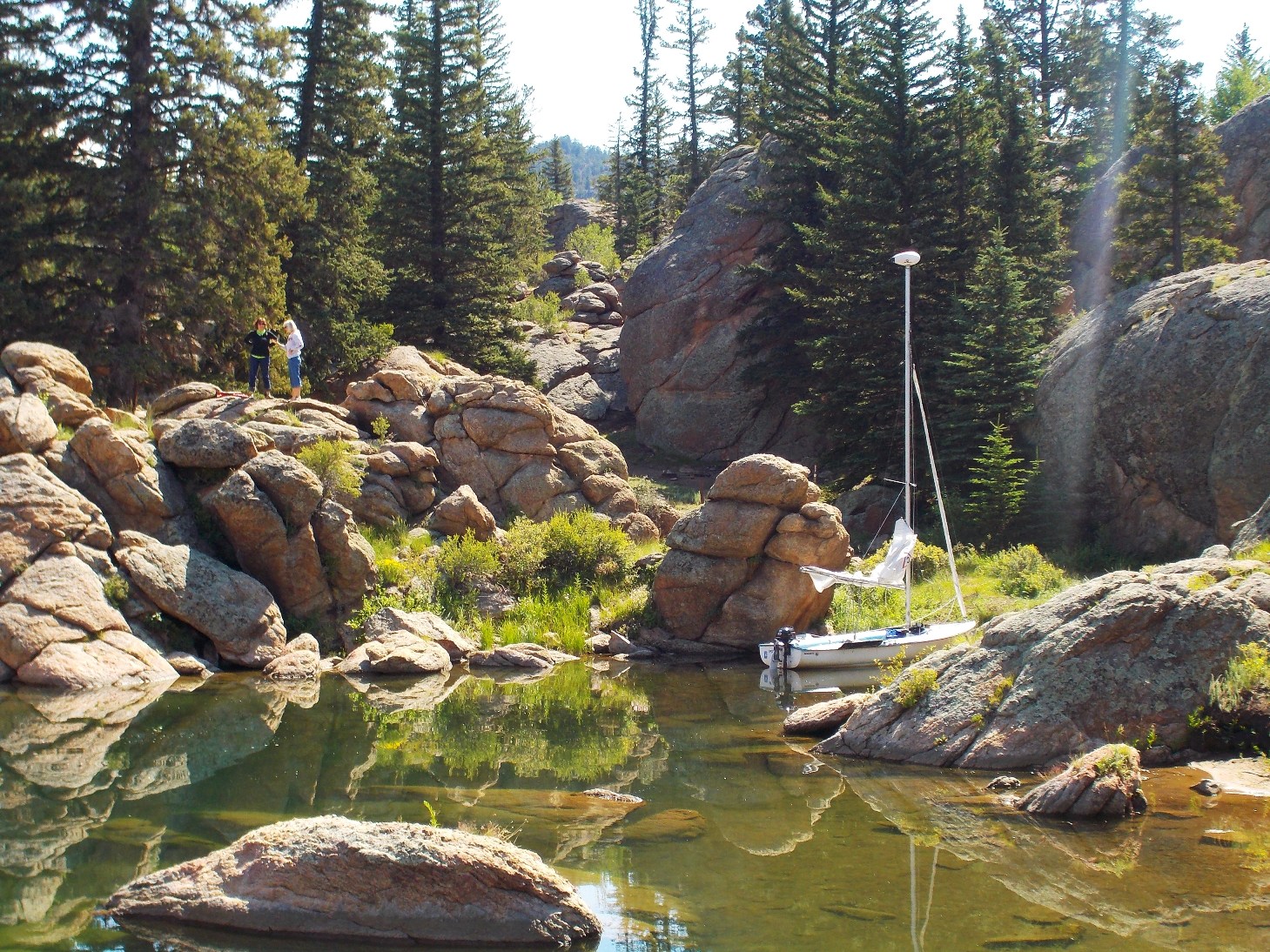
Below Elevenmile Res, Colorado (8600 ft elevation South Park)
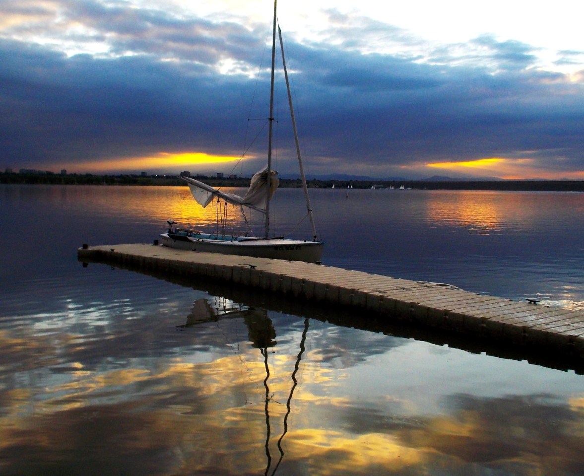
Below Cherry Creek res, Colorado (Denver)
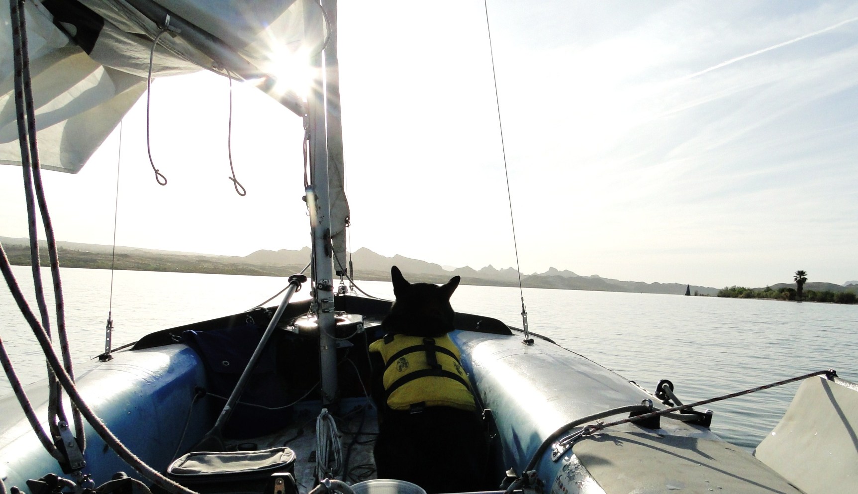
Below: Lake Havasu, Arizona